Strain Gauge Application
Stress Measurements using strain gauges (strain gage) are needed to validate design of a structure and to ensure that the structure is able to withstand designed load. While most of the structural stresses are readily predicted using Finite Elements, it is necessary to do strain gauging and measure the actual stress/strain at the areas that are difficult or impossible to plausibly simulate. Such locations typically include welds, critical load bearing members with intricate geometries, and uncertain load distribution etc.
Tension, compression, shear and torsional stresses can be measured with strain gauges by accurately determining the actual material strain or deformation.
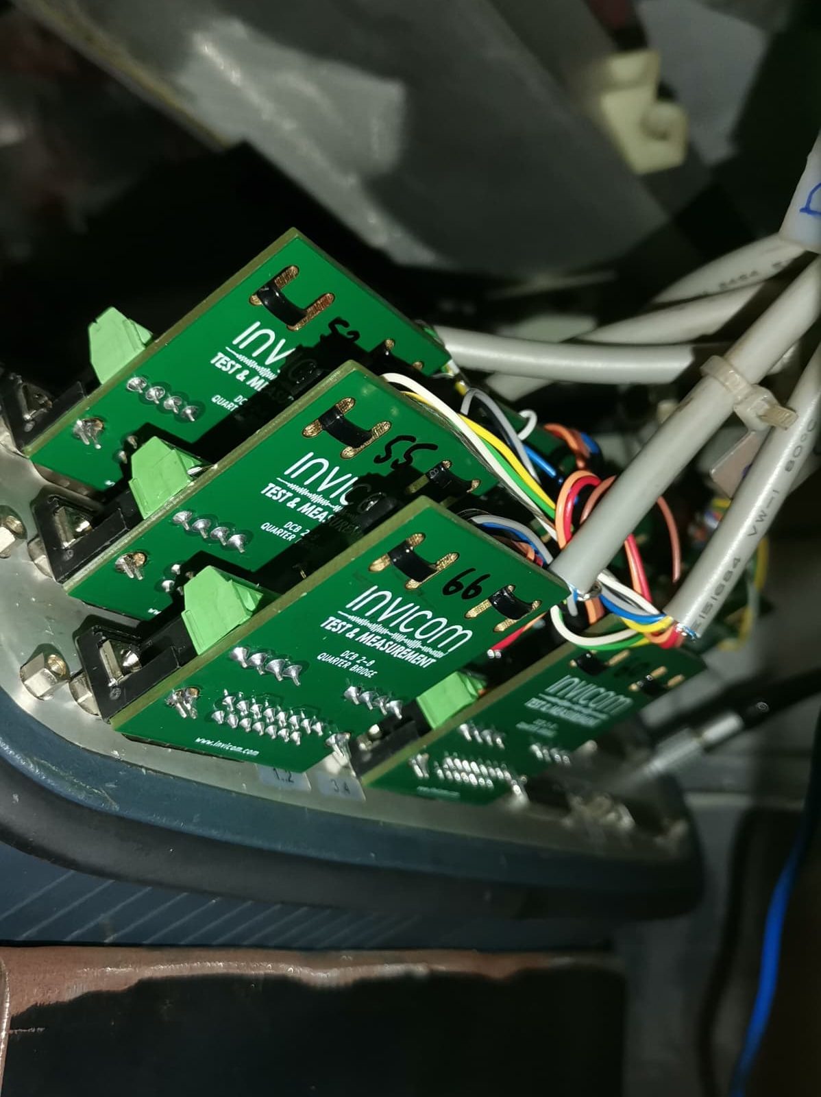
Strain gauges are constructed from resistive material that exhibits linear change in resistance with respect to deformation. Most strain gauges are able to linearly measure deformation within 2-3% of strain, or 0.02 strain units. Careful arrangement of multiple gauges in wheatstone circuit, called wheatstone bridge, gives measurable output voltage corresponds to the change in resistance. Changes of fraction of ohms produce millivolts of signal to be measured with sensitive data acquisition systems. imc Data Acquisition Systems are equipped with internal bridge completion, sense wiring and 24 bit delta-sigma analog to digital conversion to obtain highly accurate strain measurements.
Since wheatstone bridge output is proportionate to the input voltage, the data acquisition system requires to have capability to measure the voltage ratio in mV/V (output mV / input Voltage) rather than the output signal alone.
Arrangement of strain gauges in the placement and wiring determines which deformation is to be measured, axial, bending or both. For Torsional strain measurement, different kind of gauges are used.
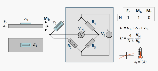
Quarter Bridge: The most simple strain gauge measurement is by using quarter bridge. The data acquisition system needs internal quarter bridge completion circuit to achieve this. Thermal compensation is not possible with quarter bridge.
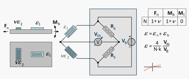
Poisson Half Bridge: Using 2 similar gauges, and known poisson ratio (transverse strain coefficient) of the material, temperature influence is cancelled.
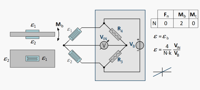
Bending Half Bridge: Using 2 similar gauges on either side of the member to enable the measurement of pure bending. Axial force is cancelled out as well as any temperature influence.
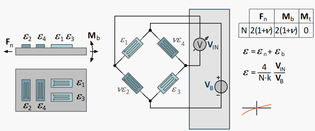
Poisson Full Bridge: If both axial and bending measurement is required, or if there is only one accessible surface, poisson full bridge can be used to compensate for temperature influence. It achieve higher sensitivity by employing transverse strain correction (poisson ratio)
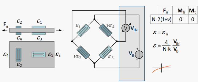
Axial Full Bridge: If pure axial strain is to be measured, this method can be applied. Similar to poisson full bridge, it achieve higher sensitivity by employing transverse strain correction (poisson ratio), with temperature compensation. Any bending strain will be cancelled out and only pure axial strain is sensed.
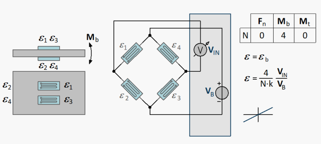
Bending Full Bridge: High sensitivity with pure bending measurement. Temperature is compensated. As opposed to axial full bridge configuration, it measures pure bending strain and axial strain is cancelled out.
Accuracy can be further enhanced by using high impedance sense lines to detect the actual input voltage at the bridge rather than at the point of power supply. Data acquisition systems like imc Cronos series and imc ARGUSfit series provide either one or 2 lines of sense for high accuracy and able to drive long cables even for quarter bridge arrangement.
Not only the need for sophisticated, accurate and stable data acquisition system, the successful strain gauge measurement is governed by the following:
Surface preparation: Surface must be well prepared with multi-grit sanding with cross patterns.
Gauge placement: for dynamic applications where stress gradient is very steep, the gauges must be placed at exact locations as well as orientations with tight tolerances.
Bonding: Gauges must be bonded with suitable cement. Cements are available for short term or permanent, which normally require heat assisted curing.
Wiring: Cables to connect strain gauges and data acquisition system must be twisted, shielded and of good quality. All the cables must be properly secured to not give any false signal due to cable straining.
Protection: Strain Gauges must be protected against moisture and to some extent, physical contact. The protection should not chemically affect the gauge material and insulation.
Here are general steps we normally take to do the strain gauging:
Strain Gauge Installation
Installation of strain gauge requires careful and meticulous work. Care and attention are needed to obtain a reliable and accurate measurement.
1. Location of Strain Gauges
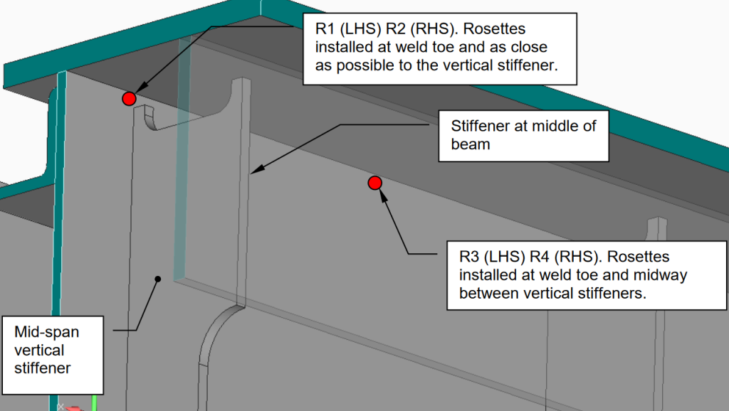
Location of strain gauges are determined by structural engineers. Points of measurement are where the structural weakness is susceptible due to welding, stress concentration or other factors. Locations are marked on the drawing in the test procedure. The figure below shows the example of such marking.
2. Surface Preparation
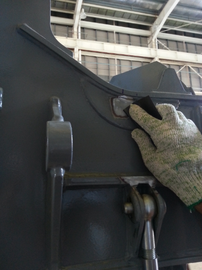
Marked areas are sanded with cross patterns, removing coatings, rusts etc, and smoothed uneven surface until flat and shine. Better surface gives better bonding, thus providing good quality to the measurement.
3. Gauge Attachment
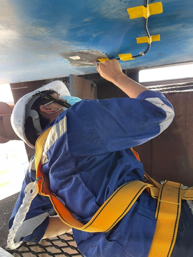
After surface preparation has finished, the surface is cleaned with special reagent to remove dust, oil residue or any foreign matters. Afterwards, the exact location and orientation of strain gauge is marked. Then, the strain gauge is bonded to the surface using cement specific to the material and test condition.
4. Wiring
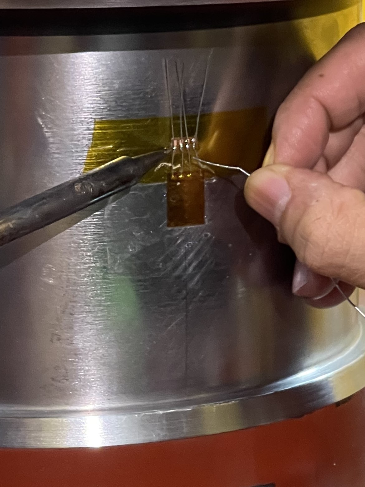
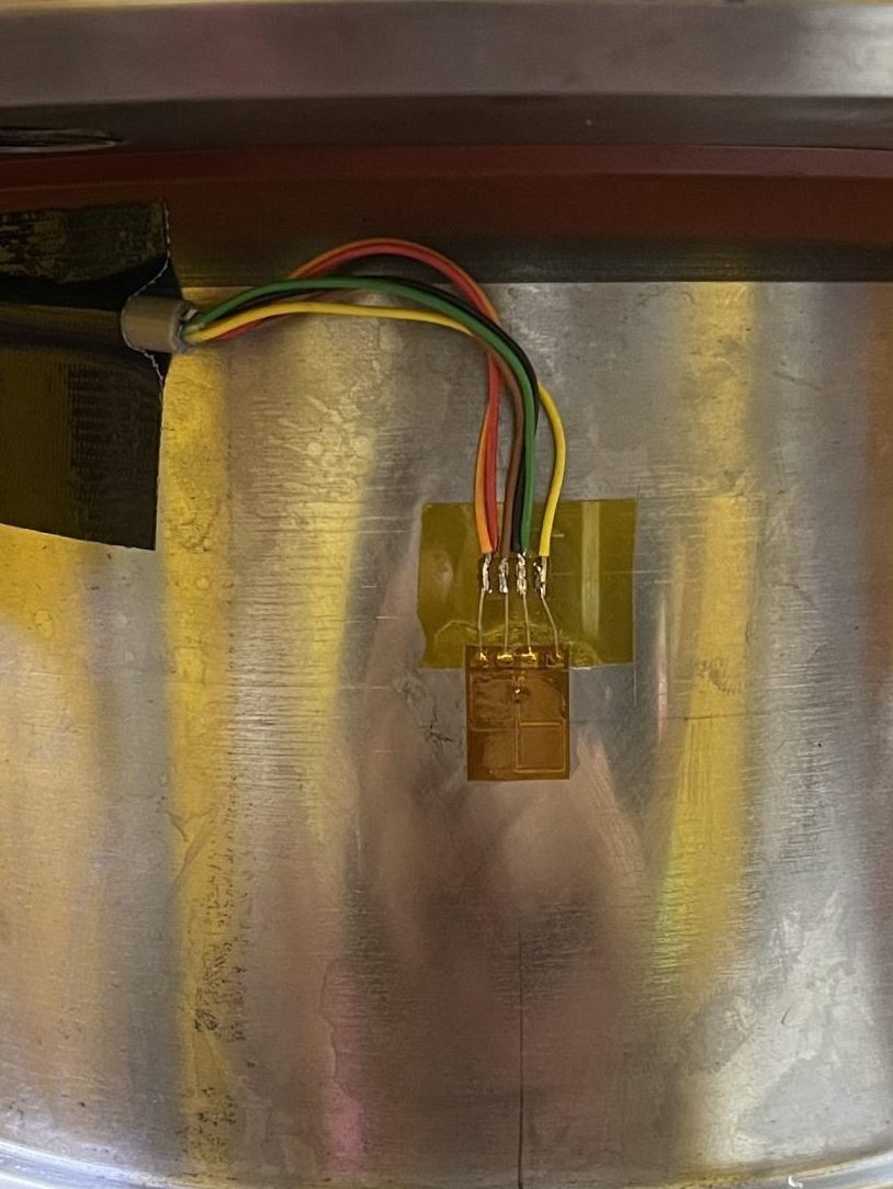
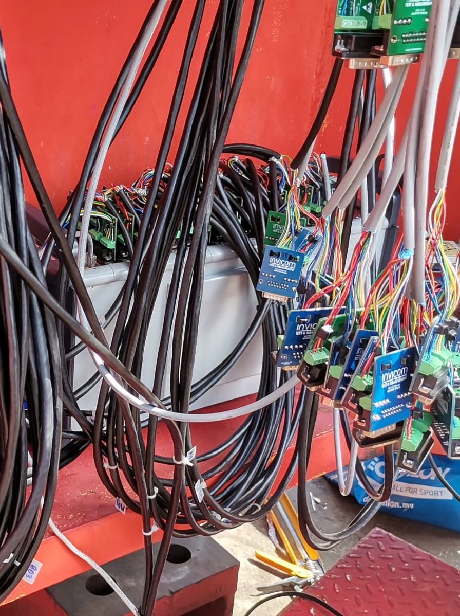
Cable is either soldered to the strain gauge or crimped to a connector of the strain gauge depending on the situation. The cable will be then drawn to the data acquisition system and secured properly the entire length.
5. Protective Coating
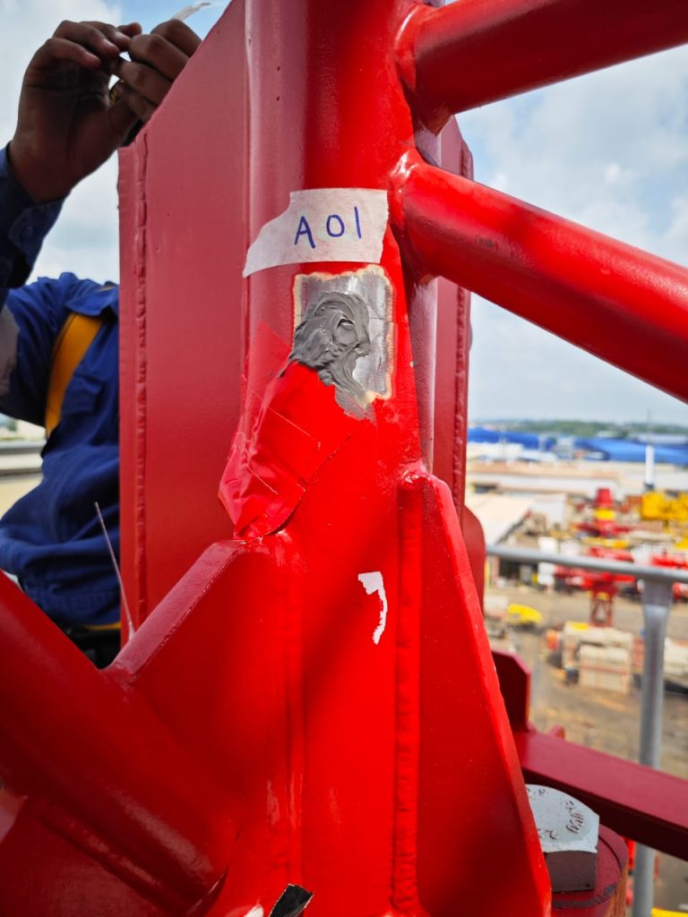
Finally, protective coating is applied to weather-proof and prevent accidental damage to the strain gauge.
Please feel free to talk to one of our experts, who are more than willing to share their experience for your strain gauging needs. Our efficient installation methods and large data acquisition channels are able to meet your small or large scale strain measurements within very short times.
Last Updated on January 8, 2025 by Invicom Webmaster

