Structural Health Monitoring (SHMS)
Structural health Monitoring Systems (SHMS) are the integrated solutions that come from many years of experience in field data acquisition, back end calculation and user interface development and deployment. Users obtain engineering results and structured reports due to integration of Monitoring and analysis systems at the back end. Our back end servers utilize secure web service and programming tools for the best performance, reliable, easy and automated data processing.
The owners are able to host server software and backend systems at commercial cloud providers, self on-premise or subscription to our cloud services.
We provide SHMS systems for Bridges, Tunnels, Towers, Telco or Cellular BTS Towers, Offshore Oil Platforms and many more.
We partner with leaders in design and manufacture of diverse range of precision instruments and our team of software/hardware developers. Our systems are well suited for structural monitoring, damage detection, structural integrity evaluation, historical data analysis and many more. We integrate variety equipment from our renowned Manufacturers:
- imc Test & Measurement GmbH
- Metra Mess und Frequenztechnik (MMF)
- Structural Vibration Solutions (SVIBS ARTeMIS)
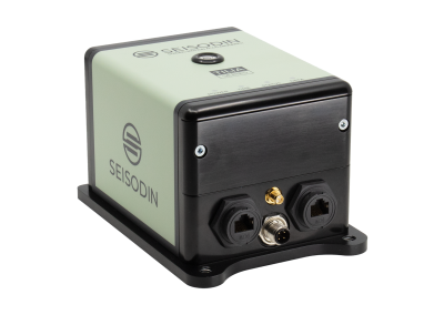
- Seisodin Aps
- Earth System Srl
- Dynamic Design Solution (FEMtools)
and variety of ancialiary equipment suppliers for fittings, cables, solar power modules, ATex enclosure etc.
We provide SHMS systems as a package, pre-deployment measurements, or partial monitoring components, that can be integrated into customer’s platform.
Are you looking for details on specific sensor types for a particular structure, or do you need a cost-benefit analysis for a new monitoring project? Please feel free to contact us.
Offshore Structural Dynamic Monitoring
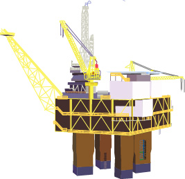
Invicom integrates and provides Offshore Structural Dynamic Monitoring systems for short or long term monitoring of offshore platforms. Incorporating variety of sensors, measurement systems and evaluation software.
Telco Tower Monitoring
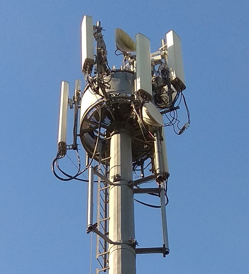
Telco or Cellular towers (BTS Towers) house valuable equipment. Safety and integrity of these towers are sometimes overlooked and can lead to undesirable consequences.
Bridge SHMS
Bridges need continuous and periodic assessment of the condition. Using a comprehensive SHMS system enables proactive maintenance by using sensor data and data analysis to detect anomalies or monitor degradation before things become critical.